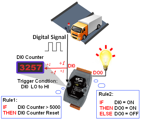
DI channel value can be used as evaluation criteria for IF condition statement. For Digital Input operations, the criteria can be: ON , OFF, ON to OFF, OFF to ON, and Change for evaluating if the DI channel should initiate a state change. In addition to basic Digital Input control function, WISE also provides DI Counter function. DI counter value can also be used as evaluation criteria for IF condition statement. Select an operator from“=”, “>”, “<”, “≥” or “≤” and compare DI Counter value with the specified value. In addition, DI Counter provides Counter Change as evaluation criteria. With various functions provided, the DI logic programming work can be easier.
DI Attribute Setting
- WISE-71xx, 72xx, 75xx, 790x
- WISE-580x
- WISE-284x, 52xx, 224x
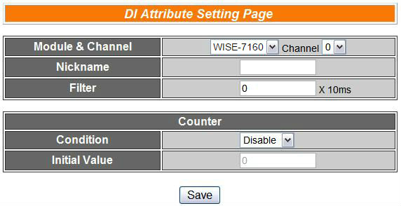
The DI attribute setting page is shown as below:
Follow the following steps:
-
Specify the channel you are going to configure by selecting channel index from the dropdown list of channel field in “Module & Channel” section.
-
Input Nickname for each I/O channel, this nickname will be displayed on the “Channel Status” page.
-
Input the time interval in the “Filter” field. The time interval for filter is the minimum duration a signal has to present to make a change to the DI channel value. If the signal last shorter than this filter time interval, this signal change will be determined to be noise instead of a valid signal change. Default Filter time interval will be 0 and this value must be multiples of 10ms, for example, a setting of 20 would mean a 200 ms filter (20 x10 ms). The range of filter is between 0 and 65535.
-
Please set the trigger criteria for triggering the counter to count. There are three criteria: HI to LOW, LOW to HI and Status Change. If you select “Disable” indicates that the counter of this DI channel will not function.
-
You can set the initial value of the counter in the “Initial Value” field. This counter will start counting from the initial count value. The default initial value is 0 and the range of initial value is between 0 and 65535.
-
Repeat steps 1 ~ 5. After all DI channel settings are completed, click “Save” button to save the changes.
For XW-Board:
The XW-Board DI Channel Setting page is shown as follow: (using XW107 as an example)
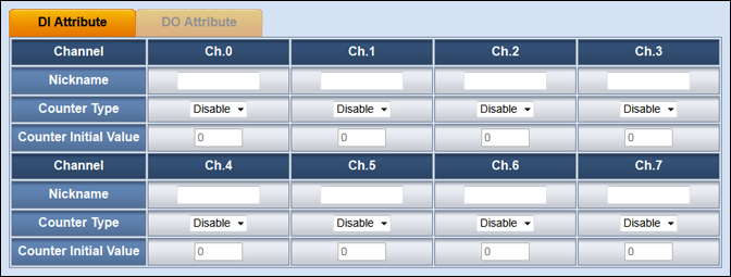
The settings are as follow:
- Nickname:For users to define nicknames for each I/O channel, this nickname will be displayed on the “Channel Status” page.
- Counter Type:Specify the counter type to be Falling edge detection (ON-to-OFF) or Rising edge detection (OFF-to-ON); if you select “Disable” indicates that the counter of this DI channel will not function.
- Counter Initial Value:You can set the initial value of the counter in the “Counter Initial Value” field. This counter will start counting from the initial count value. The default initial value is 0 and the range of initial value is between 0 and 65535.
For I-7000 module:
The I-7000 module DI Channel Setting page is shown as follow: (using I-7052 as an example)
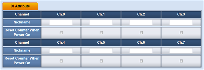
The settings are as follow:
- Nickname:For users to define nicknames for each I/O channel, this nickname will be displayed on the “Channel Status” page.
- Reset Counter When Power On:When the “Reset Counter When Power On” is selected, it means the system will reset the DI counter of this I-7000 module to the default value when WISE-580x power on.
Please note: the DI channel counter of I-7000 module is counting by default Falling edge detection (ON-to-OFF), if you would like to select other counting type, please use DCON Utility to set up the counting type.
For XV-Board:
The XV-Board DI Channel Setting page is shown as follow (using XV107 as an example)
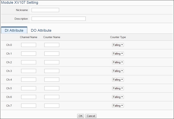
The settings are as follow:
- Channel Nickname: For user to define nicknames for each I/O channel, these nicknames will be displayed on the “Channel Status” and “Rule Setting” pages.
- Counter Nickname: For user to define nicknames for each DI counter, these nicknames will be displayed on the “Log Header” and “Rule Setting” pages.
- Counter Type: Specify the counter type to be “Falling” (ON-to-OFF) or “Rising” (OFF-to-ON).
For I-7000/DL DCON module:
The I-7000/DL DCON module DI channel setting interface is shown as below (using I-7060 as an example)
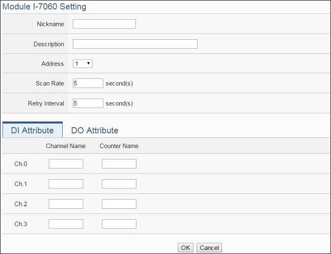
The settings are as follow:
- Nickname: For user to define nickname for the module and the I/O channels, these nicknames will be displayed on the “Channel Status” and “Rule Setting” pages.
- Description: The Description field provides a space for the user to make a brief description of this module.
- Address: The address will be the DCON address of this I-7000/DL DCON module, please make sure the address is the same as the settings of the module, if the setting is not accurate, the connection for WISE-52xx/WISE-224x to the I-7000/DL DCON module will be failed.
- Scan Rate: Input the time interval for WISE-52xx/WISE-224x to periodically retrieve the I/O channel data of this I-7000/DL DCON module, the setting range will be 0 ~ 65535 seconds.
- Retry Interval: The time interval to wait for WISE-52xx/WISE-224x to repeatedly send command again when WISE-52xx/WISE-224x sends command to the I-7000/DL DCON module and get no response. The unit will be second. The setting range will be 3 ~ 65535 seconds.
Please Note: For I-7000/DL DCON modules, the counting mode of the DI channel counter is Falling. You can change the counting mode by DCON Utility.
DI Attribute Rule Setting
-
DI Condition:
-
DI Counter Condition:
-
DI Counter Action:
Identify the status of DI Channel to be ON or OFF, if the result matches the evaluation criteria, the Action will be executed. The action also can be executed when there is a change to the DI Channel status, such as: “ON to OFF” or “OFF to ON”, or when there is any “Change” to the DI Channel. The action will be executed only once and only at the moment when DI Channel experience a change.
| DI Channel | Status | Description | Condition Statements |
| DI Channel N Status | ON | Identify if DI is ON | Continue to be TRUE when the status matches the criteria |
| OFF | Identify if DI is OFF | ||
| ON to OFF | Identify if DI is OFF and previous DI status is ON | Turn to be TRUE only once when there is a change | |
| OFF to ON | Identify if DI is ON and previous DI status is OFF | ||
| Change | Identify if the DI status is different from the previous status |
Identify the value of DI Counter to be equal to, greater than, less than, equal to or greater than, equal to or less than the specified value, if the result matches the evaluation criteria, the Action will be executed. The action also can be executed when there is a change to the value of the DI Counter.
| DI Counter | Operator | Variable | Description | Condition Statements |
| DI Counter Value of Channel N | = > < ≥ ≤ |
User-Defined Value | Using a user-defined value to compare with the DI counter value of channel N. | continue to be TRUE when the status matches the criteria |
| Internal Register | Using the internal register value to compare with the DI counter value of channel N. | |||
| AI Channel Value | Using AI channel values of module to compare with the DI counter value of channel N. | |||
| AO Channel Value | Using AO channel values of module to compare with the DI counter value of channel N. | |||
| DI Channel Counter Value | Using DI channel counter values of module to compare with the DI counter value of channel N. | |||
| DO Channel Counter Value | Using DO channel counter values of module to compare with the DI counter value of channel N. | |||
| Input Register Value | Using input register values of module to compare with the DI counter value of channel N. | |||
| Holding Register Value | Using holding register values of module to compare with the DI counter value of channel N. | |||
| MQTT Subscribe Topic Message Value | Using MQTT subscribe topic message value to compare with the DI counter value of channel N. | |||
| Amazon Web Services Subscribe Message Value | Using Amazon Web Services subscribe message value to compare with the DI counter value of channel N. | |||
| Microsoft Azure Subscribe Message Value | Using Microsoft Azure subscribe message value to compare with the DI counter value of channel N. | |||
| IBM Bluemix Subscribe Message Value | Using IBM Bluemix subscribe message value to compare with the DI counter value of channel N. | |||
| Change | - | Identify if there is a change to the value of DI Counter | Turn to be TRUE only once when there is a change |
When the condition is TRUE, reset the DI Counter value(for I-7000 modules: the DI Counter will be reset to default value, for others: the DI Counter will be reset to 0).
| DI Counter | Action | Description | Execution Type |
| DI Counter Value of Channel N | Reset | Reset DI Counter value | One Time |
DI Attribute Application Example
- WISE-71xx, 72xx, 75xx, 790x
- WISE-580x
| Scenario | Example Document | ||
|
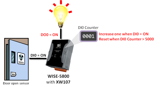
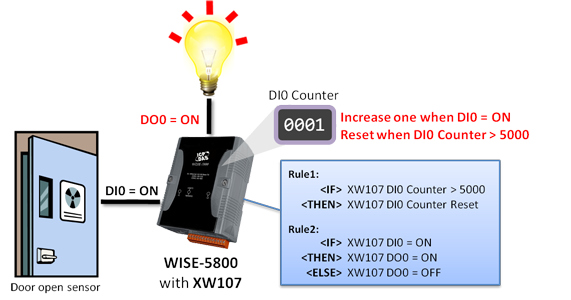
Assume an access control sensor and a light that are respectively connected to the DI channel 0 and DO channel 0 on a WISE-5800 controller that is equipped with a XW107 XW-Board. Each time when the door is open, the sensor will send out a digital signal, and the DI channel 0 will receive an ON signal, and then the DO0 channel will be changed to ON; the light will be ON to light up the area nearby the door. When the door is shut, the sensor will send an OFF signal to DI channel 0, at this time, DO channel 0 will again being changed back to OFF and the light will be turn off at the same time. In addition, WISE-5800 controller allows to calculate the access frequency via the DI Counter function. The DI counter will reset to 0 when it reaches certain preset amount such as: 5000 times, and will re-calculate the frequency from 0. |
|
||
| Graphic Illustration | |||
 |
|||

